The first step to a properly installed solar panel system is understanding how the equipment works from the inside out, and that includes their wiring. A solar panel installation’s main purpose is to convert sunlight into electricity, and the wiring for a solar panel is what enables this process to take place. In addition to transmitting the energy, however,
smart wiring ensures that all the power delivered from the solar panels reaches its intended destination, be it a battery bank, an inverter or a home grid, while avoiding loss or safety hazards.
Choose a wire type. Solar wires come in different types, and each is designed to be used in specific circumstances and capacities. The two most commonly used types are PV wire, which is a very flexible, durable, solar-resistant material especially built for solar outdoor applications, and THHN wire, which is designed to be used in conduits, trays, or other protected, in-door environments. Since solar panels are installed outdoors,
the best option for panel to inverter wiring is the more durable and naturally UV-resistant PV wire. The same is true for connections between the inverter and a battery bank, since most solar panel installations’ batteries are stored outside.
Choose the right wire gauge. It is crucial for solar systems to be wired with the right wire gauge, not just to ensure compliance, but for efficiency and safety reasons. The wire gauge refers to how much current the wire can safely carry to its destination before overheating, and as such,
the lower its gauge number, the more current it can handle. Of course, the best wire gauge to go with depends on the total current output of the system and the total distance to be traveled between the solar panel and the inverter or battery bank. As an example, a 12 AWG wire is perfect for short runs and low current, but a 4 AWG is needed for higher current or longer lines.
A wire size calculator can be used in combination with the total amps and feet amount to determine the right wire with which to wire the solar system.
The Importance of Wire Management
It is needless to say, that
proper wire management not only ensures that an installation is neat and professional but predefined malfunction risks as well. Wire should be initially disposed of to minimize the possible risks and to enhance performance at large. The wires should be secured to prevent damage from different environmental factors. The secured wires should have no loose ends preventing arcing and fires. The wires should be placed in conduit and wire covers.
One of the most important things is to label all the wiring, which can be of ultimate benefit later on when you are conducting maintenance.
The properly designed wiring system is easy to inspect and maintain. If you stick to these basics, you will ensure the efficiency, safety and performance of the solar system for its whole lifecycle. Do not forget that nothing is insignificant when you are selecting, installing, and managing wiring for your solar electric system.
Minimizing Power Loss in PV Systems
The resistance of wires and connections refers to one of the largest obstacles on the way to effectiveness and reduced function and design of a photovoltaic system. Several factors cause power loss including the resistance of wires, connections, and the physical layout of the system. It is essential to ensure that you eliminate these factors and maintain their minimized effect.
Ways to reduce a voltage drop
One of the most common problems of the PV systems is the excessive voltage drop across the wires. One of the ways to reduce it is to use
thicker wires with the lower AWG. Because a thicker wire has less resistance, there would be less voltage drop across the longer wires. In fact, changing a 16 AWG wire to a 10 AWG wire can reduce the voltage drop more than two times, when a distance is 100 feet and the current is 5A. Another way to solve this issue is to plan the structure of the PV array in a way that it would require the minimum amount of wires. Shorter length of a wire would also cause less resistance and would help keep the voltage level consistent. Lastly, it is beneficial to use
MPPT charge controllers because they are able to adapt to different voltage levels, helping to keep your PV system working on its maximum efficiency.
Arrangement of the components for efficiency
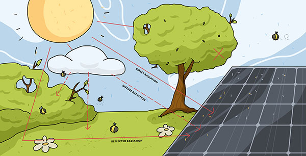
The arrangement is another important part of a PV system, able to determine its efficiency. It is better to ensure that as few wires would be used as possible to minimize the amount of power lost. The optimal arrangement is the positioning of the inverter and the battery as close to the PV panels as possible. As the electricity flow a shorter distance, lower voltage drop will take place. Moreover, the higher the amount of sunlight that PV panels receive, the higher the efficiency of your system. The most efficient way is to use adjustable mounts that change its angle depending on a season.
Although both approaches are popular and efficient enough, on the one hand, you can choose a high voltage, and on the other hand, it will be possible to decide in favor of high amperage. In the former case, a high voltage and low current DC supply is used, which will have less power loss over a greater distance. The advantage of this method will be the possibility of implementation in small systems, as well as in cases where the distance between the solar modules to the inverter is significant. In the latter case, when it is necessary to prefer the high amperages method, we are talking about selecting thicker wires and larger components that can work on greater current. However, a similar choice will also be associated with the necessity to spend more money on these materials. Finally,
high-voltage systems may not be the best option because they require special handling and specific equipment due to the current high voltage, they can cause high safety risks. Depending on your preferences and the parameters of the implementation between your PV system and inverter, you can choose one of these strategies. However, any of them will increase the effectiveness of the resulting approach, as it will be able to reduce the power loss of the implemented PV system.
The importance of the reframed recommendations related to this approach lies in the fact that they should be used in real-world applications depending on the characteristics of a particular PV system. As a result, it will be possible to choose one of the approaches that can be used with a solar system. Finally, the decision must be observed beginning with the installation wires definitely and completing the selection of various elements of the PV system and the arrangement of these solar panel systems.
Wiring Solar Panels in Series
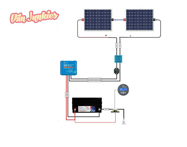
When solar panels are wired in series, the positive circuit is connected to the negative side of the next, forming a continuous chain. This wiring configuration increases the overall voltage while maintaining the current equal to the individual panel. For example, a set of five 12V panels wired in series would produce a system with 60 volts but keeping the current output unchanged. It is appropriate for systems requiring long wire runs between the array and the charge controller or inverter as
higher voltage arrays see reduced energy losses over distance. However, series connections raise the system’s susceptibility to shading, meaning that even partial shading of one panel would significantly diminish the output for the entire string.
Wiring Solar Panels in Parallel
In parallel, both positive and negative sides are connected to a single point so that the current is added while the voltage remains the same, still yielding a 12V system. In the previous example, parallel wiring of five 12V panels kept the voltage equal to 12V but increased the current by five times. This is a favorable configuration where partial shading is present. Because each panel operates independently, shading only one of the panels would not diminish the rest of the system’s performance. Nevertheless,
parallel wiring is liable for demanding thicker cables able to handle the current flow, particularly for larger arrays, potentially increasing the system cost.
Hybrid Series-Parallel Configurations
Hybrid configurations are those that combine series and parallel wiring depending upon the specific system’s requirement. For instance, if two strings of five 12V panels are wired in series, resulting in two strings of 60V, these two strings may then be wired in parallel to double the system current while maintaining 60V output. This type of configuration is useful because it allows the system designer to choose the number and type of units that optimize efficiency and shading resilience. In this way, it may be concluded that
hybrid configurations combine the best features of both series and parallel wiring and offer a built-in warranty in superstructed assemblies. Hence, if you decide to install solar panels in a complicated location where space, shading, and efficiency are critical considerations, use hybrid series-parallel configurations.
Indeed, understanding your solar power system’s needs and choosing the right wiring configuration can make a difference. These needs include but are not limited to distance, shading, and load requirements that shape the decision-making process. Consequently, remember that your goal is to maximize efficiency and minimize your solar power system’s loss while adhering to the lifetime performance guarantee. As concerns wiring specifics,
basic set up in series and parallel is not the only wiring technique that should be employed. Charge controllers and regulators should also be properly integrated to protect the solar power system from overcharging and excessive discharge. Moreover, the handler will need to learn a series step-by-step guide to help wire the solar panels. First and foremost, it is necessary to mention that
wiring in series implies connecting the positive terminal of each unit to the negative terminal of the next unit. This will allow the system worker to connect all panels to the system.
For connecting the panels, we have to use a proper connector to attach the positive terminal of the first panel to the negative terminal of the next one. This process has to be followed through all the panels. The connection made through this way is known as a series connection. At the end, the final positive and negative terminals have to be connected to your charge controller, inverter, or storage batteries, matching the voltage requirements. This type of connection is useful for long-wire runs because the higher voltage obtained by serial connections will lessen the energy loss.
Process of Parallel Connection
The parallel connection of the panels will increase the amperage, keeping the voltage the same as a single panel. Both of the positive terminals have to be connected together, as well as the negative terminals. Use a proper branch connector to attach the positive terminals and do the same with the negative terminals. Ensure that all the panels are equally distanced from the connection point. Later, connect the new and positive negative leads to the charge controller of your power storage system and ensure that it can handle the increased amperage.
Parallel connections, which are able to minimize the effect of panel shading, are also better than serial connections.
Integration of Charge Controllers and Regulators
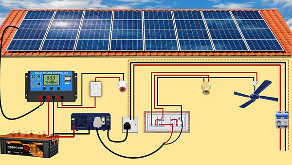
The charge controllers and regulators are required for ensuring maintenance of battery conditions and to manage the system efficiently. They regulate the flow of electricity from the solar panels to the battery and from the battery to the load, thereby reducing the risk of overcharging and over-discharge of your battery.
Choose a Charge Controller: Make sure it is compatible with the voltage and current specifications of your solar panel array and battery bank. Connect the Solar Panel(s) to the charge controller’s solar input terminals. If you have connected multiple panels in series or parallel, connect the combined output leads to these terminals. Connect the Battery Bank to the charge controller’s battery terminals, taking care to get the polarity right to avoid damage. Connect the Load, if any, to the charge controller’s load terminals. Wiring in this manner will allow you to draw power directly from the panels or battery and will also provide over-discharge protection.
Program the Charge Controller for your battery type and capacity.
Many modern charge controllers come with presets for different types of batteries and may also offer custom settings.
By ensuring that you follow these wiring techniques carefully and properly integrate charge controllers, you can boost the performance and life expectancy of your solar power system significantly.
Wiring Connectivity and Inverter Selection
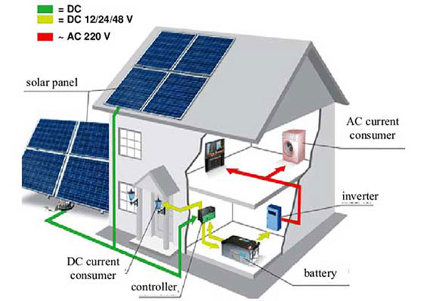
Choosing the right inverter and ensuring proper wiring connectivity is also an important part of installing a solar power system. The inverter is what enables the system to convert the direct current from your solar panels into alternating current that most of your household appliances and the electric grid use. You must make informed decisions in this regard to ensure that your system provides the desired efficiency, safety, and reliability.
Inverter Requirements and Matching Panels
To enhance the overall efficiency of your solar power system, it is vital to match the output characteristics of your solar panel array to the input requirements of the inverter. For example, the total voltage and current output of your panels, both when wired in series or parallel, should be coordinated with the inverter’s operational range or convert parameters. If, for example, your inverter’s input voltage range is 200V to 600V, then the combined voltage of your solar panels should be within this range when wired in series. This maximum DC input voltage of the inverter should be available in the datasheet, as well as the nominal DC input voltage and maximum input current. Using this information prevents or avoids mismatching for the risk of underperformance or damage. In addition, using microinverters or power optimizers are more advanced approaches to managing the generated electricity. In the first case, a microinverter is installed onto each panel to convert it into AC at the source, which, with optimizers enhances energy production, particularly in the partial shading or complex panel orientation-up directions. The slight form of power optimizer is connected from each panel to a central inverter to send DC that has been already optimized.
Connection to the Grid
Interconnection of the solar power system to the electric grid should felt to meeting the specific standards and regulation, as well as the local requirement and passing inspections with the installation of elevation of array. It requires special permits or application and custom agreement only. This is a list of steps where to apply for the Interconnection would be to your local utility company providing data about your solar power system.
Install a Bi-directional Meter is necessary for net metering. This meter will record the amount of power you draw from the grid and the surplus electricity your solar panels feed into it.
Ensure Your Inverter is Grid-Tie Compatible; in other words, it can sync its power signal output with the grid AC power on terms of both voltage, frequency, and phase.
Pass a Safety Inspection. The safety inspection is to confirm that this installation meeting all of your local and state electrical codes and your utility’s requirements for such an installation.
Connecting your solar panels to the grid you can utilize power when your system is underproducing and sell overproduced electricity back to the utility, hence, increase your electricity saving and return on your investment. For safety reasons and for your benefit, ensure compliance with all the local regulations and standards.